2D scans
A 2D scan is a flat image of the foot, captured from a scanner or imported from a file, used as a design base.
Adding a 2D scan
Location: Project page → sidebar → 2D scan
Mode and file count
The dialog has two independent settings: what you scanned, and how many images it takes.
Mode tells LutraCAD what the image shows, whether you scan it or import it:
| Mode | Use it when |
|---|---|
| Blueprint | The image is an imprint or outline on paper. |
| Foot | The image is the sole of the foot itself. |
File sets how many images you are working from:
| Option | What it does |
|---|---|
| 1 file | Captures or imports a single image and uses it for both feet. |
| 2 files | Captures or imports the left and right foot separately. |
Mode and File are separate choices, not one combined setting. Both are radio buttons, and LutraCAD remembers them for the next scan.
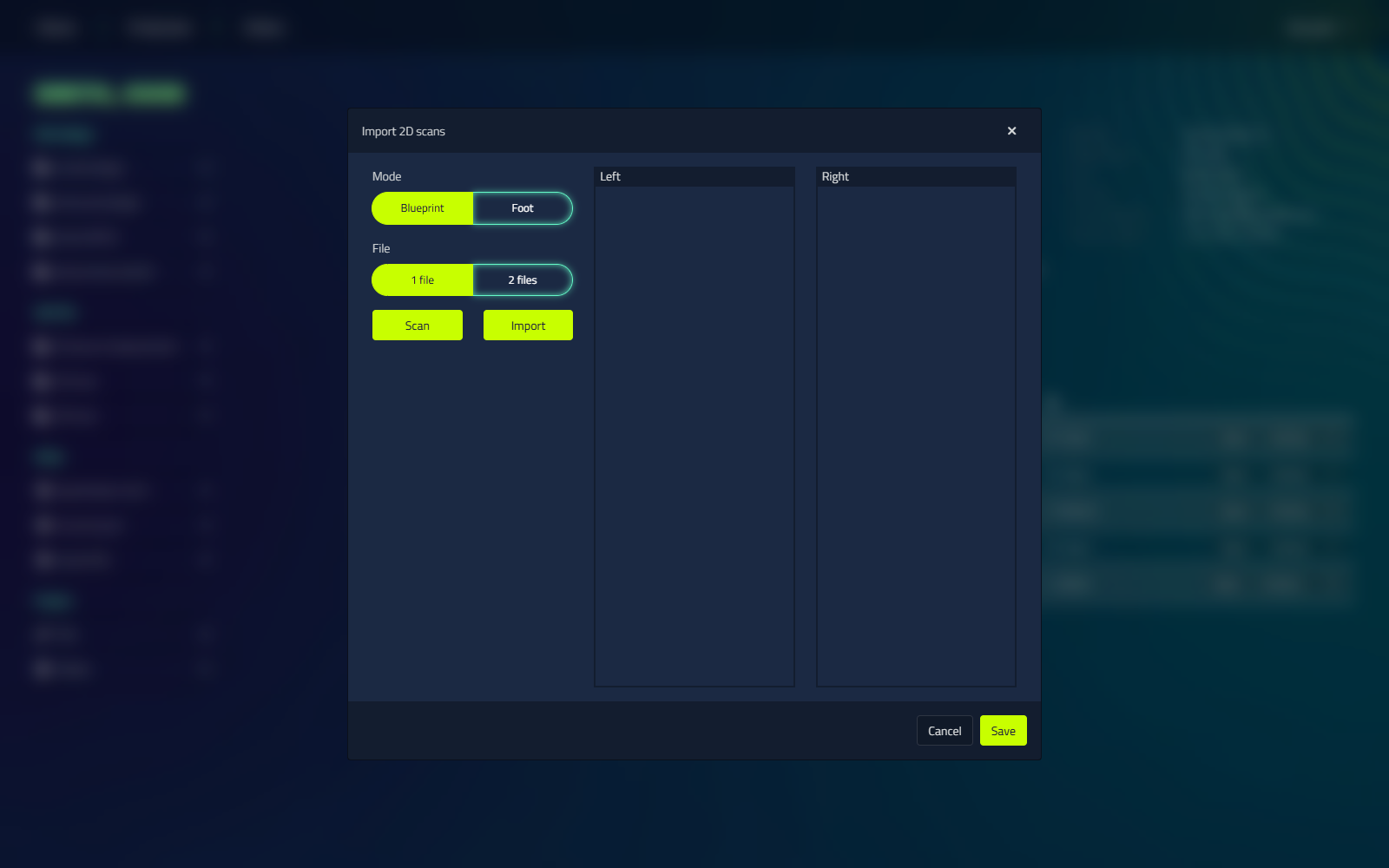
Scan or import
Each image panel has its own Scan and Import button, so with 2 files you can capture one side and import the other.
- Scan captures the image from the connected scanner.
- Import loads an image file instead. Supported formats:
.jpg,.jpeg,.bmp,.png.
LutraCAD controls almost all 2D scanners on the market, with no manual calibration.
Adjust the image
Once an image is loaded, rotate and flip buttons appear above it:
| Control | What it does |
|---|---|
| Rotate counter-clockwise | Rotate the image 90° counter-clockwise. |
| Rotate clockwise | Rotate the image 90° clockwise. |
| Flip | Mirror the image horizontally. |
You can also drag inside the image to reposition it, to frame the usable area.
Save
Save stores the scan on the project.
Viewing a 2D scan
Open the 2D scan document from the project. The viewer is shared with pressure measurement and photo documents, so which buttons appear depends on the document type.
| Button | What it does |
|---|---|
| Swap left and right (icon button) | Swap which side is labeled left and which is right. Available for 2D scan and pressure measurement documents. |
| Export | Save the scan image as .jpg, then offers Open directory to browse to the file. |
Calibrating a 2D scan
To take true-to-size measurements from a 2D scan, calibrate it first with the Scale 2D action in the design environment. Include a ruler or another object of known length in the scan.
- Open the 2D scan and click Scale 2D.
- Click a start point, for example the 0 mark on a ruler in the scan.
- Click an end point, for example the 10 cm mark.
- Type the real length in mm and press Enter.
The scan is now scaled so measurements match the real foot.
See pressure measurements for adding pressure data to a project.