CNC Milling
A milling table is a reusable profile that tells your CNC machine how to mill a product: table size, cutters, feed rates, pockets and the output file format. You build a table once, then pick it whenever you mill a product. This page covers where tables live, creating one, milling a product from a table, and a full reference of every setting.
Where milling tables live
All milling tables are managed from one place: the top bar → Production → New milling project. This opens the Select milling table dialog, which lists every saved profile.
| Button | Location | What it does |
|---|---|---|
| Add table | Top | Create a new profile (opens the settings dialog) |
| Import | Top | Import a profile from an .lrss file |
| Edit | Per row | Open the settings for that profile |
| Select | Per row | Start a milling production with that profile |
| Close | Bottom | Close without starting a production |
Create a milling table
- Top bar → Production.
- Click New milling project.
- In the Select milling table dialog, click Add table.
- Work through the settings groups (all covered in the settings reference below).
- Click Save.
- Back in the dialog, click Select on your new table to start a milling production with it.
Build the table once. Next time, just pick it in the list and click Select. You can Export it to an .lrss file to share with another workstation, or Duplicate it to make a variant.
Edit an existing milling table
Editing runs through the same dialog as creating, so you reach it the same way even though you are not starting a new profile.
- Top bar → Production.
- Click New milling project.
- In the Select milling table dialog, find the profile you want and click Edit on its row.
- Change the settings you need (all covered in the settings reference below).
- Click Save.
A production does not keep its own copy of the settings, it refers back to the profile. Editing a profile therefore also affects milling productions that were created with it earlier.
Saving an edited profile shows no warning at that moment. The next time you open a milling production that was made with this profile, LutraCAD notices the settings differ and shows:
"The table settings have changed compared to previous production, please check the document."
Check that document before you mill from it again. Machine files you already exported are not affected; the new settings apply when the document is reopened and the output is generated again.
The action buttons at the bottom of the same dialog let you copy, export, delete or save the profile.
| Button | Location | What it does |
|---|---|---|
| Duplicate | Bottom left | Copy the profile as a new entry |
| Export | Bottom left | Save the profile as an .lrss file |
| Delete | Bottom left | Delete this profile (asks for confirmation) |
| Cancel | Bottom right | Close without saving |
| Save | Bottom right | Save all settings |
Deleting a table is permanent. Double-check that you have the right table selected before you confirm.
Milling a product
Once your table is ready, return to the Select milling table dialog and click Select on the profile you want. LutraCAD opens a new milling table document using those settings. This is where you place your parts on the cutting table and export the machine file to load on your CNC machine.
Add work to the table
Click Add to place production items on the table. The Select production dialog lets you pick an existing production order or import one.
| Option | What it does |
|---|---|
| Search | Search and pagination help you find an order in a long list. |
| Filters | Filter by type and status, plus an archive toggle, to narrow the results. |
| Import | Bring in an order (.l3z / .stl) or a milling file. Importing a milling file prompts you for the insole thickness and edge thickness. |
Arrange and export
The milling table document lays your parts out on the cutting table.
| Control | Function |
|---|---|
| Add | Add production items (insoles, shells, parts) to the milling table |
| Replace table | Open the milling-table dialog to swap the cutting table |
| Text field | A label shown on the table for a screenshot only; it is not milled |
| Export | Generate the machine file (the extension comes from the table's File extension setting) |
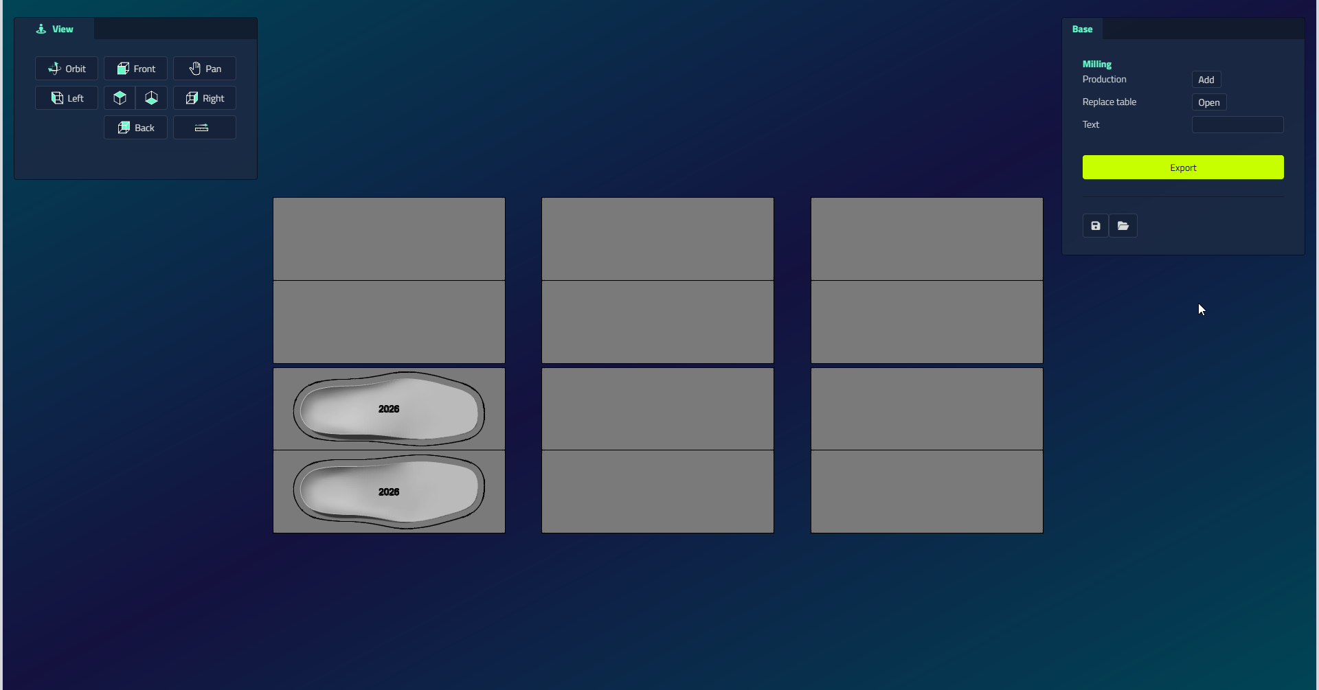
To arrange items, drag them into position on the table. Select one and use Rotate (orient it in its bounding box), Duplicate, or Delete.
Warnings before export
Resolve any warning before exporting:
- A milling-error banner appears if a placed item does not fit the table, sits too high, or overlaps another item.
- A table-modified warning appears if the milling table's settings differ from a previous production of the same design. Confirm it to continue.
- When you export, a milling disclaimer may appear. Confirm it, and tick Do not ask again to skip it in future.
Settings reference
The settings dialog is organised into groups. Fill in the ones that apply to your machine. Note that some groups are hidden depending on the brand you choose (in particular, most cutting groups are hidden for DeskProto).
Basic settings
| Field | Type | Options / notes |
|---|---|---|
| Document type | Dropdown | Insole design / Midsole design |
| Name | Text | Profile name |
| Brand | Dropdown | Default / ISEL / DeskProto / DUO CAM |
| Strategy | Dropdown | Offset / Spiral (hidden for DeskProto) |
| Dimensions | Dropdown | 2D / 3D (hidden for DeskProto) |
| Strategy contour | Dropdown | Layered / Spiral (hidden for DeskProto) |
| Two sides | Checkbox | Enable two-sided milling |
| Flip axis | Dropdown | X on table / Y on table / X in pocket / Y in pocket (only when two-sided is enabled) |
| File extension | Dropdown | .gcode / .iso / .nc / .pim / .cnc (hidden for ISEL and DeskProto) |
| Number of decimals | Number | Coordinate output precision (hidden for ISEL and DeskProto) |
Use the Brand field to match the G-code language your machine expects:
- Default: standard G-code.
- ISEL: G-code specifically for ISEL machines.
- DeskProto: LutraCAD produces the geometry and hands the actual CAM (toolpaths) to DeskProto externally (see below).
- DUO CAM: standard G-code for milling machines with two spindles.
With the DeskProto brand, LutraCAD produces only the geometry, and the toolpaths are generated externally in DeskProto (a separate program) via a .dpj project file. That is why the toolpath, contour, cutter and feed-rate groups below are hidden for this brand.
- Open button: select the
.dpjDeskProto project file. - Save button: export the current state as
.dpjto open in DeskProto.
Milling settings
| Field | Type | Description |
|---|---|---|
| Table width | Number (mm) | Width of the milling table (X axis) |
| Table length | Number (mm) | Length of the milling table (Y axis) |
| Material height | Number (mm) | Height of the material block |
| Zero point X | Dropdown | Left / Centered / Right |
| Zero point Y | Dropdown | Front / Centered / Back |
| Zero point Z | Dropdown | Bottom / Centered / Top |
Toolpath settings
Hidden for DeskProto.
| Field | Type | Description |
|---|---|---|
| Free movement height | Number (mm) | Travel height above the material for non-cutting moves |
| Offset top | Number (mm) | Z-offset for the top-side pass |
| Offset bottom | Number (mm) | Z-offset for the bottom pass (two-sided only) |
| Create centerline | Checkbox | Add a center line to the output |
| Z-offset correction | Number (mm) | Correction for the Z zero point |
Contour settings
Hidden for DeskProto.
| Field | Type | Description |
|---|---|---|
| Enabled | Checkbox | Enable the contour cutting pass |
| Extra movement | Number (mm) | Extra travel distance around the contour |
| Support | Checkbox + Number (mm) | Add support bridges to hold the object; enter the bridge size |
| Layered | Checkbox + Number (mm) | Cut the contour in layers; enter the layer height |
| Flat | Checkbox | Cut the contour as a flat pass |
Cutter settings
Hidden for DeskProto. There are two cutter groups, one for the toolpath and one for the contour, with the same fields.
Cutter toolpath
| Field | Type | Description |
|---|---|---|
| Diameter | Number (mm) | Surfacing cutter diameter |
| Turning speed | Checkbox + Number (rpm) | Enable a custom spindle speed and enter the value |
Cutter contour
| Field | Type | Description |
|---|---|---|
| Diameter | Number (mm) | Contour cutter diameter |
| Turning speed | Checkbox + Number (rpm) | Enable a custom spindle speed and enter the value |
Feed rates
Hidden for DeskProto. There is a top group and a bottom group. The bottom group is disabled unless Two sides is on.
| Field | Description |
|---|---|
| Dip | Speed when entering the material (mm/min) |
| Normal | Standard cutting speed (mm/min) |
| Slow | Reduced speed for detail areas (mm/min) |
| Contour | Speed for contour passes (mm/min) |
The bottom group has the same four fields, applied to the bottom pass only.
Custom G-code
Hidden for DeskProto. Six text areas each insert custom G-code at a specific point in the output file. Separate files are generated for the top and bottom.
| Field | Inserted at |
|---|---|
| Toolpath start | Before the top-side pass |
| Toolpath end | After the top-side pass |
| Bottom start | Before the bottom-side pass (two-sided only) |
| Bottom end | After the bottom-side pass (two-sided only) |
| Contour start | Before the contour pass |
| Contour end | After the contour pass |
Pocket settings
Pockets are fixed positions on the table where material blocks are placed, used for automatic positioning when objects must sit in specific spots. Positions are measured from the bottom-left corner of the table.
| Button | What it does |
|---|---|
| Add | Add a new pocket row |
| Delete (per row) | Remove that pocket |
Per pocket row:
| Field | Description |
|---|---|
| X | X start of the pocket (mm) |
| Y | Y start of the pocket (mm) |
| Width | Pocket width (mm) |
| Length | Pocket length (mm) |
Auto-position settings
Defines how insoles are automatically placed into pockets.
| Field | Options |
|---|---|
| Horizontal | Left / Center / Right |
| Vertical | Front / Center / Back |
| Insoles horizontal | Checkbox: place insoles horizontally in the pocket |